PN532 Module
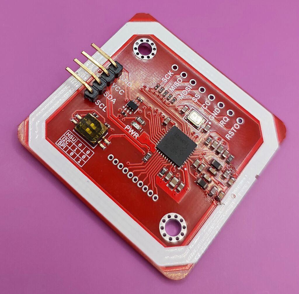
The PN532 Module is a bare NFC reader board for custom builds. It can scan and write supported NFC tags through Zaparoo. Use it when you want to mount a reader inside a case, wire it into another device, or connect it directly to a board that exposes UART or I2C.
If you only want a reader you can plug in and use, choose the PN532 USB instead.
Platforms
This is not a finished USB reader. Expect wiring, soldering, and some troubleshooting.
For a complete photographed build with a case and custom serial PCB, see the DIY Reader community project. That guide shows the soldering, board assembly, and case fitment, and the custom serial PCB avoids the form factor and voltage issues found with some generic USB-to-serial adapters.
Many PN532 modules sold online are clones. They can work with Zaparoo, but read range and board quality vary by seller and revision.
What you need
For the usual USB UART setup, you need:
- A PN532 module.
- A USB-to-serial adapter, such as a CH340, CP2102, or FT232RL board.
- Wires or pin headers.
- Basic soldering tools.
Wire the module
UART is the most practical connection for a Zaparoo host because it appears as a normal serial port.
Most modules ship with the DIP switches already set to HSU, which is the UART mode used for USB-to-serial adapters. Check the switch labels before wiring the module.
For HSU/UART wiring, use the labels on your PN532 board and USB-to-serial adapter:
- Connect
GNDon the PN532 module toGNDon the adapter. - Connect
TXorTXDon the PN532 module toRXorRXDon the adapter. - Connect
RXorRXDon the PN532 module toTXorTXDon the adapter. - Connect
VCCto a voltage your PN532 module supports.
Check the markings on your module before connecting power. Some boards accept both 3.3V and 5V; others are stricter.
Configure the reader
Zaparoo Core can auto-detect PN532 UART readers by default. If auto-detection does not find the module, add it to your config.toml with the pn532uart driver.
Linux-based platforms usually expose the USB-to-serial adapter as /dev/ttyUSB0 or /dev/ttyACM0:
[[readers.connect]]
driver = "pn532uart"
path = "/dev/ttyUSB0"
On Windows, use the COM port shown in Device Manager:
[[readers.connect]]
driver = "pn532uart"
path = "COM3"
On macOS, use the matching /dev/cu.* device:
[[readers.connect]]
driver = "pn532uart"
path = "/dev/cu.usbserial-1234"
I2C
Direct I2C connections are for embedded setups, such as a Raspberry Pi-style board with an exposed I2C bus. I2C is supported, but it does not auto-detect. You must add the reader to config.toml.
Set the module to I2C mode and configure the bus device:
[[readers.connect]]
driver = "pn532i2c"
path = "/dev/i2c-1"
Troubleshooting
Module not detected
Check these first:
TXon the module goes toRXon the adapter, andRXgoes toTX.- The DIP switches match the configured transport: HSU/UART or I2C.
- The module has stable power. If you are using a generic USB-to-serial adapter and the reader is unreliable, compare it with the DIY Reader build that uses a custom serial PCB.
- For UART, the USB-to-serial adapter appears as a device path or COM port.
- For I2C, the
pathinconfig.tomlmatches the I2C device you connected the module to.
Scans are unreliable
Move the module away from metal, dense wiring, and other electronics. If the tag only reads at very close range, the module may be a low-quality clone.
Writing fails
Keep the tag still on the reader while writing. If writing MIFARE Classic tags fails repeatedly, test with an NTAG tag before replacing the reader.
Where to buy
For a ready-to-use reader, use the PN532 USB page instead.
Original hardware:
- Elechouse - Official PN532 module
Other modules are usually listed as PN532 Module:
- Amazon
- eBay
- AliExpress
- Local electronics shops
Known listings submitted by users: