PN532 Module
The PN532 module is a bare PCB NFC reader perfect for DIY projects and custom builds. While it requires more setup than the USB version, it's extremely affordable and flexible.
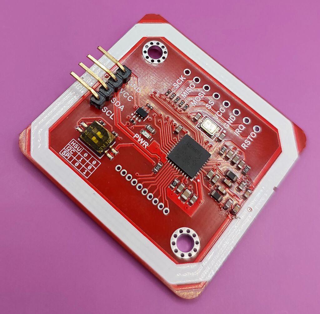
While the PN532 module is excellent on paper, most sold online are low-quality clones. They'll generally still work but often with poor read range. Despite this, they remain the best option for custom microcontroller builds.
This is not a ready-to-use reader - it's a bare PCB module for custom projects. You'll need a USB-to-serial adapter and basic soldering skills.
Features
- Extremely affordable - Starting at around $3 USD
- Compact footprint - Perfect for embedding in custom projects
- Excellent read range - Quality modules read up to 5cm
- Multiple interfaces - UART, I2C, and SPI support
- Flexible - Full control over implementation
- Great learning project - Perfect for beginners to electronics
Requirements
Essential Components
- PN532 Module - The NFC reader module itself
- USB-to-Serial Adapter - Common options:
- CP2102 module
- CH340G module
- FT232RL module
- Soldering Equipment - For connecting wires/headers
Optional Components
- Pin headers or JST connector
- Jumper wires
- Project case
- 5V power supply (if not using USB power)
Driver Configuration
Driver Details
- Driver IDs:
pn532,pn532uart,pn532i2c,pn532spi - Primary Transport: UART (via USB-to-serial adapter)
- Alternative Transports: I2C, SPI (for advanced projects)
- Platforms: All platforms
- Enabled by default: Yes
- Auto-detect: Yes (for UART)
Hardware Setup
UART Connection (Most Common)
Connect the PN532 module to a USB-to-serial adapter:
PN532       USB-Serial
-----       ----------
VCC    -->  5V or 3.3V
GND    -->  GND
TX     -->  RX
RX     -->  TX
Set the PN532 DIP switches to UART mode. They usually come set this way.
Software Configuration
Auto-detection (Recommended):
The PN532 UART is auto-detected by default. Just plug in the USB-to-serial adapter!
Manual Configuration:
Add to your config.toml if auto-detect doesn't work:
Linux/MiSTer:
[[readers.connect]]
driver = 'pn532uart'
path = '/dev/ttyUSB0'
Windows:
[[readers.connect]]
driver = 'pn532uart'
path = 'COM3'
macOS:
[[readers.connect]]
driver = 'pn532uart'
path = '/dev/cu.usbserial-1234'
Advanced: I2C Configuration
For direct I2C connections (e.g., Raspberry Pi GPIO):
[[readers.connect]]
driver = 'pn532i2c'
path = '/dev/i2c-1'
Set DIP switches to I2C mode.
Advanced: SPI Configuration
For SPI connections:
[[readers.connect]]
driver = 'pn532spi'
path = '/dev/spidev0.0'
Set DIP switches to SPI mode.
Platform-Specific Notes
MiSTer
The PN532 module with USB-to-serial adapter works excellently on MiSTer. Auto-detection typically works out of the box.
Raspberry Pi/Linux
For direct I2C or SPI connections:
- Enable I2C/SPI in
raspi-config - Install required kernel modules
- Add user to
i2corspigroups
For UART via USB-to-serial:
sudo usermod -a -G dialout $USER
Windows
Install the USB-to-serial driver for your adapter chip (CH340, CP2102, etc.). Usually automatic via Windows Update.
Known Issues
Variable Build Quality
- Quality varies significantly between vendors
- Cheaper modules may have issues
- Look for reputable sellers with good reviews
Poor Read Range
Cause: Low-quality inductors on cheap modules
Symptoms: Module functions but only reads at very close range (<1cm)
Solution: Replace the inductors with quality components (advanced)
Connection Problems
USB-to-Serial Adapter Issues:
- Poor voltage regulators may not power the module properly
- Some cheap adapters are unreliable
- Try a different adapter if you have connection issues
Soldering Required
This is a bare module - you must solder wires or headers. Not suitable if you don't have soldering equipment.
Troubleshooting
Module Not Detected
- Check wiring - Verify TX→RX and RX→TX are not swapped
- Check DIP switches - Must be set to correct mode (UART)
- Check power - Module needs stable 3.3V or 5V
- Try different USB port - Some ports don't provide enough power
- Test USB-to-serial adapter - Verify it works separately
Scanning Issues
- Check for interference - Keep away from metal and other electronics
- Verify tag compatibility - Use ISO14443A tags (MIFARE, NTAG)
LED Behavior
- No LED - Check power connection
Where To Buy
For a ready-to-use option, consider the PN532 USB instead!
Original Hardware:
- Elechouse - Official PN532 module
Common Sources (Search for "PN532 Module"):
- Amazon
- eBay
- AliExpress
- Local electronics shops
Known Listings: