DIY Reader
This guide explains how to create a low-cost NFC reader using easily available parts. The design is compatible with Zaparoo on MiSTer, and the total cost of a single reader is approximately $10 USD in a small batch of 5 (as of 2024). If you would rather not build one, the ready-made PN532 USB reader in the Zaparoo Shop is the same reader with a case.
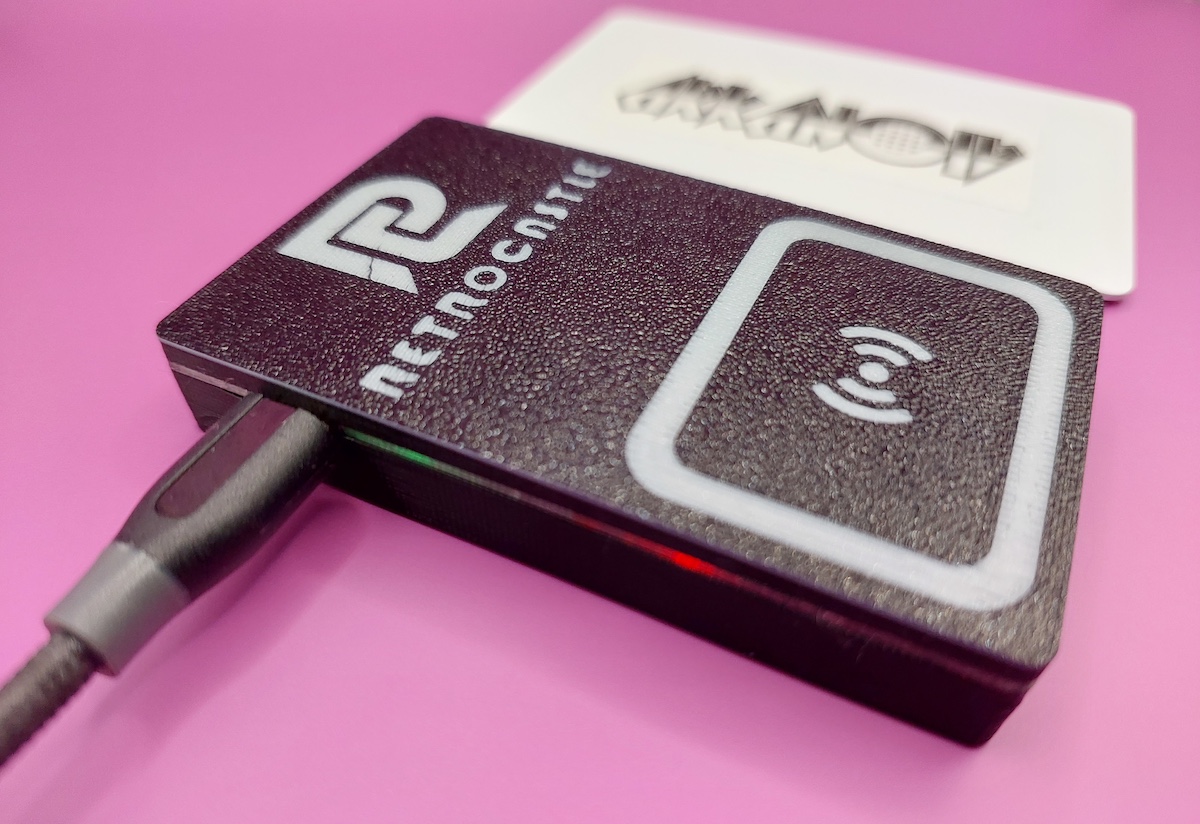
Supplies
Equipment
- Soldering iron
- Solder
- Flux
- 3D printer
Some soldering is necessary to attach the header pins that connect the serial board to the NFC module. It requires 8 through-hole solder joints, so it's a good beginner soldering project.
Access to a 3D printer is required for color switching to show the top markings and LED window, but it's also possible to use a 3D printing service and print in one color.
Parts
Feel free to shop around for components.
- PN532 NFC module - any supplier will do but must be a "PN532" module.
- 2.54mm right angle female 4-pin header - attaches to the serial board.
- 2.54mm right angle male 4-pin header - optional; attaches to the PN532 module but most modules come with one.
- 3D printing filament - if printing yourself, PLA or PETG is fine. A single case uses approximately 20g of filament.
Serial PCB
This is a custom PCB which allows the PN532 to communicate with the MiSTer over a serial USB connection. It functions the same as a standard USB to serial cable/adapter, but has a better form factor for use in a case and does not risk incorrect voltage issues that have been found in these adapters. This section will explain how to order the PCB from JLCPCB, but any PCB manufacturer will work.
Upload gerber file
From the JLCPCB home page, click the "Add gerber file" button and upload the Gerber.zip file from this repo. You'll be forwarded to the order page.
Beginning order
Scroll down to the "PCB Assembly" section and enable this option with the side toggle. Otherwise, leave all options as default and click "NEXT" on the right sidebar.
Board confirmation
Click "NEXT" on this page.
Upload BOM and CPL files
Upload the BOM-JLCPCB.xlsx file in the left file picker (BOM) and the PickPlace-JLCPCB.xlsx file in the right file picker (CPL). Then click the "Process BOM & CPL" button.
You may receive an error about the "J2 designator". Ignore this and press "Continue". This is referring to the female header pins which you will solder yourself later.
Bill of materials
There should be nothing to do on this page. Click "NEXT".
Component placements
You may see an error about components being offset when this page loads. Click "Ok". You can make sure the components aren't obviously in the wrong place, but it should be OK to click "NEXT" here too.
Quote & order
Select a "Product Description" option. Something like "DIY" is fine. Then click "SAVE TO CART".
Checkout
From here, follow the prompts to specify shipping and payment for your boards. You can also change the quantity of boards here.
And that's it. When your boards arrive you're ready for assembly.
Case
The case is 3D printed in two parts, the top and bottom. Each part snaps together, no other assembly or parts are required. Download STL files:
Print each part with a 0.2mm layer height. PLA and PETG have both tested working fine. It requires approximately 20g of filament.
If you want to make the markings on the top piece more visible, you can print it in two colors. Print the first layer in one color, print layers 2 and 3 in a contrasting color, then print the rest in the original color.
Another option to make the LED lights visible is to print the layers around the USB port in a translucent filament.
It has not been tested, but it should also be no problem to use a 3D printing service to print the case. You may have to request multiple cases to reach the minimum size requirements of the service.
Assembly
Assembly does not take long, but does require a small amount of soldering.
Soldering
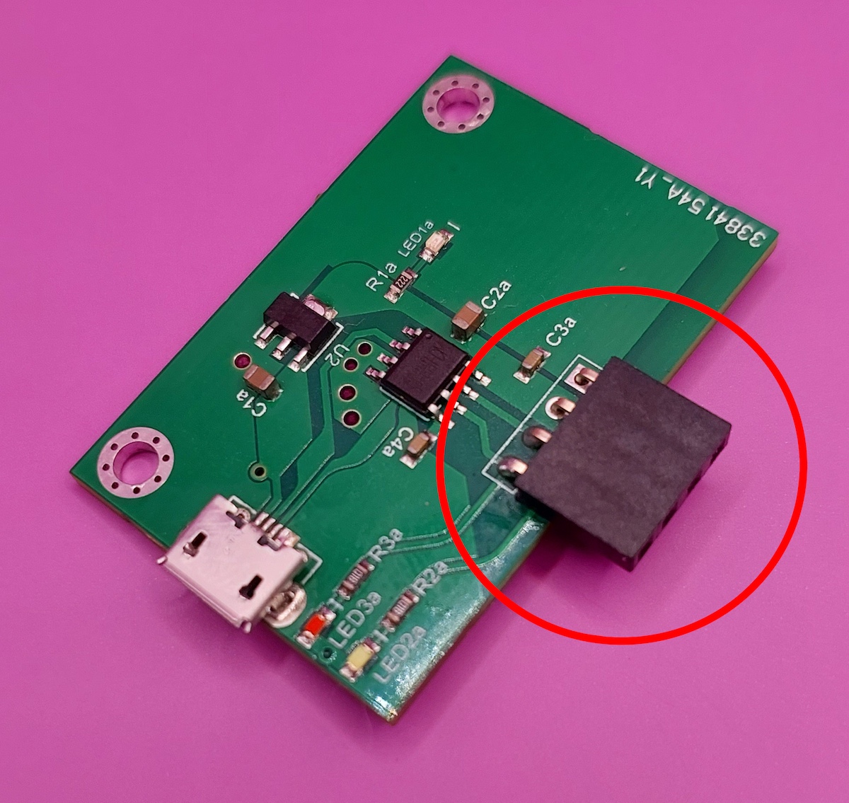
First, solder the female 4 pin header to the serial PCB, as shown in the image below. Make sure the plastic casing is flush with the PCB.
Next, solder the male 4 pin header to the PN532 module. See the image below, it needs to be soldered into the part with only 4 holes, not the side with 8 holes.
It's important that this one goes on straight too, and it can be a little tricky to get right. You can hold one edge straight with your nail or helping hands, then solder the opposite side. Kapton tape may also help to hold it in place.
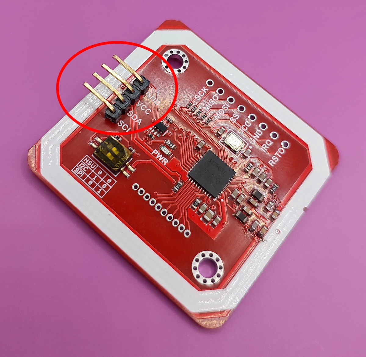
If you touch the male pins at any point, make sure to give them a quick clean with alcohol. This can affect the connection to the module.
Lastly, check the DIP switches on the PN532 module, next to the connector you soldered. They should be set to "HSU". This is how they usually come by default.
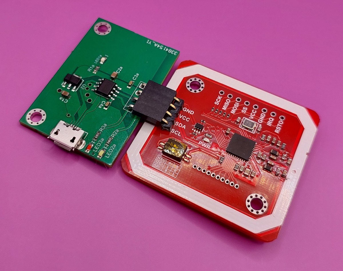
Now you can connect the 2 boards together like shown.
Case
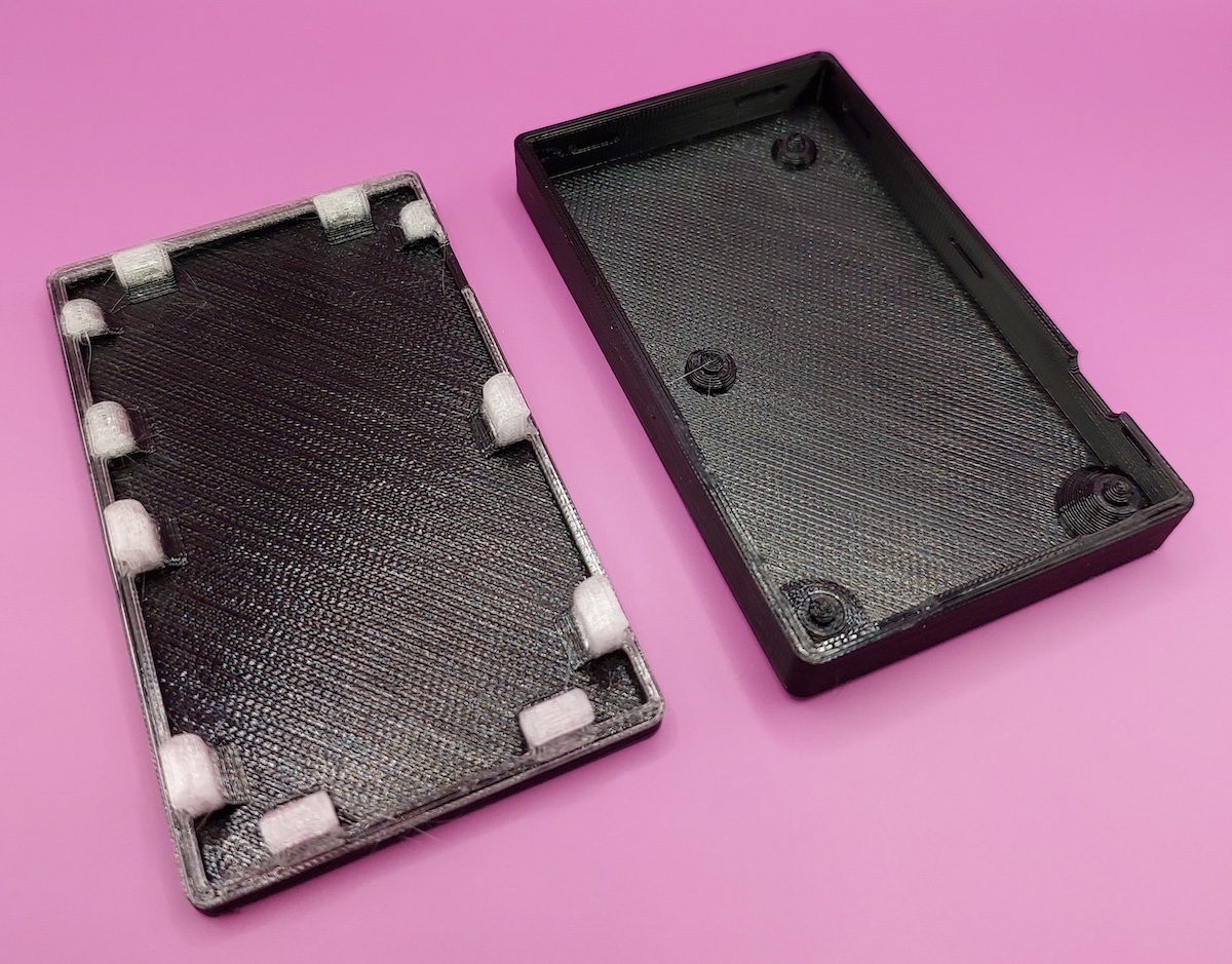
Drop the assembled boards into the bottom half of the case, aligning the mounting holes with the indentations in the case and the micro USB slot.
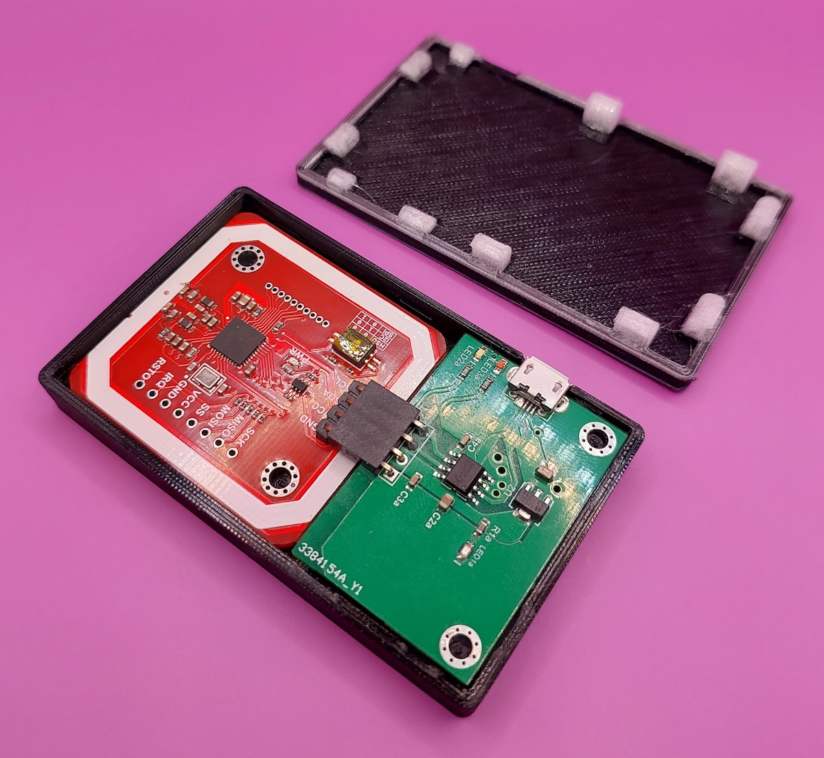
Then, place the top piece on top and push it in place into the bottom piece. They will snap shut together. It can take a little bit of force to make them snap together, but it should not be too difficult.
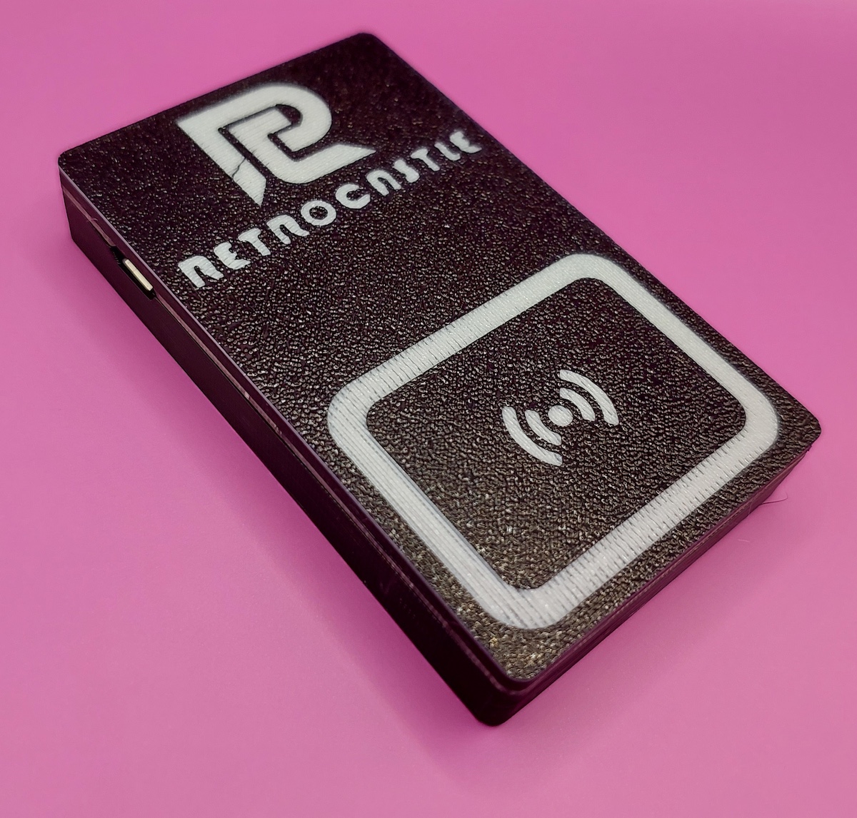
That is the build done. The reader is plug and play with Zaparoo on a MiSTer FPGA and Commodore 64.
Contributors
- RetroCastle - serial PCB design and testing.
- wizzo - case design and documentation.
- Retro Frog - case design advice.